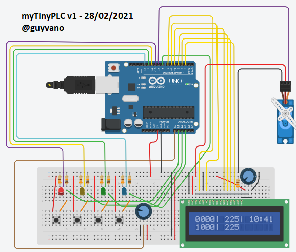
La version 1.2 vient de sortir, avec une bonne trentaine de nouvelles instructions. Et maintenant, quatre temporisations (timers) sont disponibles !
Voici le tableau mis à jour des instructions :

Explication sur les nouvelles instructions :
- 0 à 9 : correspondent à ces mêmes valeurs (en base 10, sur un chiffre) que l'on utilise par la suite avec les fonctions 66 à 69 (set timer delay) pour définir la durée en secondes des temporisations (0 à 9 secondes).
- 10 : Lecture de l'entrée analogique (le potentiomètre). La rotation complète du potentiomètre va de la valeur 0 à la valeur 9. En lisant cette entrée, on peut l'affecter à une temporisation.
Cette entrée analogique peut aussi être lue numériquement avec les instructions 70 à 79.
- 25 : Lecture de la mémoire 5. La version précédente n'avait que quatre mémoires.
- 26 à 29 : Lecture des temporisations (timers) 6 à 9. Les timers sont associés aux mémoires 6 à 9. On utilisent les instructions 56 à 59 (Write timer) pour faire démarrer les temporisations.
- 55 : Ecriture de la mémoire 5.
- 56 à 59 : Ecriture des mémoires 6 à 9 associées au démarrage des timers 6 à 9. L'écriture de la valeur logique 1 fait démarrer le timer. On peut connaître l'état d'un timer par une lecture (instructions 26 à 29). Avant son démarrage, un timer est au niveau logique zéro. Il passe à 1 dès son lancement, puis il repassera à zéro à la fin de sa durée définie, soit par défaut, ou bien telle qu'elle a été définie avec les instructions 66 à 69. L'écriture d'un zéro dans la mémoire associée au timer n'arrête pas ce dernier, il reste à 1 tant que sa durée n'est pas terminée. Le maintien d'un 1 dans la mémoire associée au timer ne le fait pas repartir pour une nouvelle durée. Pour le relancer, il faut que sa mémoire associée repasse à zéro, puis à 1 afin de lancer le timer à nouveau.
- 60 et 61 : On écrit la valeur logique 0 ou bien 1.
- 66 à 69 : On définie la durée en secondes des timers 6 à 9 en utilisant le chiffre donné précédemment comme valeur de la durée.
- 70 à 79 : Lecture numérique de l'entrée analogique (potentiomètre). On a définit dix valeurs analogiques différentes (de 0 à 9) pour l'entrée analogique. Si la valeur analogique est 0, on aura la valeur logique 1 comme résultat de l'instruction 70. Si la valeur analogique est 1, on aura la valeur logique 1 comme résultat de l'instruction 71, si la valeur analogique est 2, on aura la valeur logique 1 comme résultat de l'instruction 72, et ainsi de suite jusqu'à la valeur analogique 9 qui donnera la valeur logique 1 comme résultat de l'instruction 79.
Le code de myTinyPLC en version 1.2.1 (*) :
(*) Le 9 mars, des corrections ont été faites dans l'évaluation des timers. La version précédente (1.2.0) n'était pas fiable sur les temporisations.
/* Program name: mytinyPLC-1-2-1.ino
Author: Guy Vanoverbeke @GuyVano
Program last update (dd/mm/yyyy) : 09/03/2021 - V.1 R.2 C.1
- Release name "Cool Cathy - level c.1"
Arduino IDE V1.8.13
Board: Arduino UNO R3
Function: PLC simulator with its own IL language.
Simulateur d'automate programmable doté de son propre langage IL.
-----------
Disclaimer:
This program (in other words: this code, this software or this application) is
a personal creation made as part of a hobby and it is given without guarantee
of any kind and no support is provided. It is free of rights and can be reused
freely as you wish.
*/
#include <LiquidCrystal.h>
LiquidCrystal lcd(7, 6, 5, 4, 3, 2);
//
boolean i1 = 0; // used to store input 1 value
boolean i2 = 0; // used to store input 2 value
boolean i3 = 0; // used to store input 3 value
boolean i4 = 0; // used to store input 4 value
//
boolean p[10] = {0, 0, 0, 0, 0, 0, 0, 0, 0, 0}; // potentiometer indexed position 0 to 9
//
boolean m1 = 0; // used to store memory 1 value
boolean m2 = 0; // used to store memory 2 value
boolean m3 = 0; // used to store memory 3 value
boolean m4 = 0; // used to store memory 4 value
boolean m5 = 0; // used to store memory 5 value
boolean m6 = 0; // memory 6 is tm6 starter
boolean m7 = 0; // memory 7 is tm7 starter
boolean m8 = 0; // memory 8 is tm8 starter
boolean m9 = 0; // memory 9 is tm9 starter
//
boolean pm6 = 0; // previous state of memory 6
boolean pm7 = 0; // previous state of memory 7
boolean pm8 = 0; // previous state of memory 8
boolean pm9 = 0; // previous state of memory 9
//
boolean tm6 = 0; // timer 6
boolean tm7 = 0; // timer 7
boolean tm8 = 0; // timer 8
boolean tm9 = 0; // timer 9
//
boolean mx = 0; // temporary memory used for Swap operation
//
boolean o1 = 0; // used to store output 1 value
boolean o2 = 0; // used to store output 2 value
boolean o3 = 0; // used to store output 3 value
boolean o4 = 0; // used to store output 4 value
boolean stack[10] = {0, 0, 0, 0, 0, 0, 0, 0, 0, 0}; // bit Stack array
boolean slow = false; // true for slow running for test and serial print instructions
boolean debug = false; // true for debug and serial prints of values
//
int ai0 = 0; // analog A0 value
int ai1 = 0; // analog input 1 value calculed
int j = 0; // loop control
int k = 0; // loop control and temporary variable
long r = 0; // temporary variable
long s = 0; // temporary variable
long t = 0; // temporary variable
long istack[10] = {0, 0, 0, 0, 0, 0, 0, 0, 0, 0}; // integer stack array
//
const int nbstp = 99; //number of maximum IL program steps
unsigned int stp[(nbstp + 1)] = {}; // IL program steps array dim = nbstp + 1
int stc = 0; // step counter
//
long ctrtm6 = 0; // current millis counter when timer 6 rised to High
long ctrtm7 = 0; // current millis counter when timer 7 rised to High
long ctrtm8 = 0; // current millis counter when timer 8 rised to High
long ctrtm9 = 0; // current millis counter when timer 9 rised to High
//
long dtm6 = 8000; // set default delay value for timer 6 in ms
long dtm7 = 2000; // set default delay value for timer 7 in ms
long dtm8 = 6000; // set default delay value for timer 8 in ms
long dtm9 = 1000; // set default delay value for timer 9 in ms
//
String ope = " ";
//
void setup()
{
//
Serial.begin(9600); // open the serial port at 9600 bps:
//
pinMode(A1, INPUT); // buton 1 as input 1
pinMode(A2, INPUT); // buton 2 as input 2
pinMode(A3, INPUT); // buton 3 as input 3
pinMode(8, INPUT); // buton 4 as input 4
//
pinMode(10, OUTPUT); // LED 1 (red) as output 1
pinMode(11, OUTPUT); // LED 2 (yellow) as ouput 2
pinMode(12, OUTPUT); // LED 3 (green) as output 3
pinMode(13, OUTPUT); // LED 4 (blue) as output 4
//
lcd.begin(16, 2);
lcd.print("mytinyPLC v1-2-1");
lcd.setCursor(0, 1);
lcd.print("project @guyvano");
delay(1000);
lcd.clear();
//
// v---- your IL program steps here / Votre programme IL ici
//
//
// Timers demo - each buton lights a led temporary with different delays
// IL program for myTinyPLC v.1.2
//
// Set timer 6 delay at 2 seconds
stp[1] = 2; // number 2
stp[2] = 66; // Set timer 6 delay
// Set timer 7 delay at 4 seconds
stp[3] = 4; // number 4
stp[4] = 67; // Set timer 7 delay
// Set timer 8 delay at 6 seconds
stp[5] = 6; // number 6
stp[6] = 68; // Set timer 8 delay
// Set timer 9 delay at 8 seconds
stp[7] = 10; // Read analog input 1
stp[8] = 69; // Set timer 9 delay
//
stp[9] = 11; // Read input 1
stp[10] = 56; // Write timer 6
stp[11] = 26; // Read timer 6
stp[12] = 41; // Write output 1
//
stp[13] = 12; // Read input 2
stp[14] = 57; // Write timer 7
stp[15] = 27; // Read timer 7
stp[16] = 42; // Write output 2
//
stp[17] = 13; // Read input 3
stp[18] = 58; // Write timer 8
stp[19] = 28; // Read timer 8
stp[20] = 43; // Write output 3
//
stp[21] = 14; // Read input 4
stp[22] = 59; // Write timer 9
stp[23] = 29; // Read timer 9
stp[24] = 44; // Write output 4
//
stp[25] = 99; // END
//
//
// ^---- end of your IL program / fin de votre programme
//
// it is a good idea to comment each line with the mnemonic of
// the instruction, for a better IL program reading and understanding
//
}
void loop()
{
//
// update IL program instruction counter
// (one IL step evaluated per loop)
//
stc = (stc % nbstp) + 1;
//
// digital input acquisition
// at least for displaying them later
// even if they are note read by the IL program
//
i1 = digitalRead(A1);
i2 = digitalRead(A2);
i3 = digitalRead(A3);
i4 = digitalRead(8);
//
// analog input acquisition
//
ai0 = analogRead(A0); // value 0..1023
ai1 = ai0 / 113; // value 0..9
//
// set corresponding p[] array element
//
j = 0;
do {
// set all to 0
p[j] = 0;
j++;
} while (j <= 9);
p[ai1] = 1; // set to 1 the corresponding p[] array element
//
//
// Start IL instruction scrutation (one IL step per loop)
//
//
// check if instruction code is a one figure number and
// if it is, consider it is a number and stack it in the integer stack
//
switch (stp[stc]) {
//
case 0:
//
istack[0] = 0;
break;
//
case 1:
//
istack[0] = 1;
break;
//
case 2:
//
istack[0] = 2;
break;
//
case 3:
//
istack[0] = 3;
break;
//
case 4:
//
istack[0] = 4;
break;
//
case 5:
//
istack[0] = 5;
break;
//
case 6:
//
istack[0] = 6;
break;
//
case 7:
//
istack[0] = 7;
break;
//
case 8:
//
istack[0] = 8;
break;
//
case 9:
//
istack[0] = 9;
break;
//
default:
// no instruction match
break;
}
//
//
// check if operation code is Read an input (instruction codes 10 to 14)
//
switch (stp[stc]) {
//
case 10:
// read analog input 1
istack[0] = ai1;
break;
//
case 11:
// read digital input 1
dwnstack();
stack[0] = i1;
break;
//
case 12:
// read digital input 2
dwnstack();
stack[0] = i2;
break;
//
case 13:
// read digital input 3
dwnstack();
stack[0] = i3;
break;
//
case 14:
// read digital input 4
dwnstack();
stack[0] = i4;
break;
//
default:
// no instruction match
break;
}
//
// check if instruction code is Read a digital memory (instruction codes 21 to 29)
//
switch (stp[stc]) {
//
case 21:
// read digital memory 1
dwnstack();
stack[0] = m1;
break;
//
case 22:
// read digital memory 2
dwnstack();
stack[0] = m2;
break;
//
case 23:
// read digital memory 3
dwnstack();
stack[0] = m3;
break;
//
case 24:
// read digital memory 4
dwnstack();
stack[0] = m4;
break;
//
case 25:
// read digital memory 5
dwnstack();
stack[0] = m5;
break;
//
case 26:
// read timer 6 (bit)
dwnstack();
stack[0] = tm6;
break;
//
//
case 27:
// read timer 7 (bit)
dwnstack();
stack[0] = tm7;
break;
//
//
case 28:
// read timer 8 (bit)
dwnstack();
stack[0] = tm8;
break;
//
case 29:
// read timer 9 (bit)
dwnstack();
stack[0] = tm9;
break;
//
default:
// no operation match
break;
}
//
// check if instruction is Read an output (instruction codes 31 to 34)
//
switch (stp[stc]) {
//
case 31:
// read digital output 1
o1 = digitalRead(10);
dwnstack();
stack[0] = o1;
break;
//
case 32:
// read digital output 2
o2 = digitalRead(11);
dwnstack();
stack[0] = o2;
break;
//
case 33:
// read digital output 3
o3 = digitalRead(12);
dwnstack();
stack[0] = o3;
break;
//
case 34:
// read digital output 4
o4 = digitalRead(13);
dwnstack();
stack[0] = o4;
break;
//
default:
// no instruction match
break;
}
//
// check if instruction is Write a digital output (instruction codes 41 to 44)
//
switch (stp[stc]) {
//
case 41:
// write digital output 1
o1 = stack[0];
// digitalWrite(10, o1);
break;
//
case 42:
// write digital output 2
o2 = stack[0];
// digitalWrite(11, o2);
break;
//
case 43:
// write digital output 3
o3 = stack[0];
// digitalWrite(12, o3);
break;
//
case 44:
// write digital output 4
o4 = stack[0];
// digitalWrite(13, o4);
break;
//
default:
// no instruction match
break;
}
//
// check if instruction is Write a memory (instruction codes 51 to 59)
//
switch (stp[stc]) {
//
case 51:
// write digital memory 1
m1 = stack[0];
break;
//
case 52:
// write digital memory 2
m2 = stack[0];
break;
//
case 53:
// write digital memory 3
m3 = stack[0];
break;
//
case 54:
// write digital memory 4
m4 = stack[0];
break;
//
case 55:
// write digital memory 5
m5 = stack[0];
break;
//
case 56:
// write memory 6
m6 = stack[0];
break;
//
case 57:
// write memory 7
m7 = stack[0];
break;
//
case 58:
// write memory 8
m8 = stack[0];
break;
case 59:
// Start timer 9
m9 = stack[0];
break;
//
default:
// no instruction match
break;
}
//
// check if instruction is to Write bit 0 or 1 (instruction codes 60 to 61)
//
switch (stp[stc]) {
//
case 60:
// write 0
dwnstack();
stack[0] = 0;
break;
//
case 61:
// write 1
dwnstack();
stack[0] = 1;
break;
//
default:
// no instruction match
break;
}
//
// check if instruction is Set Timer Delay (instruction codes 66 to 69)
// value in istack[0] must be the delay in seconds.
//
switch (stp[stc]) {
//
case 66:
// write timer 6 delay
dtm6 = 1000 * istack[0];
break;
//
case 67:
// write timer 7 delay
dtm7 = 1000 * istack[0];
break;
//
case 68:
// write timer 8 delay
dtm8 = 1000 * istack[0];
break;
//
case 69:
// write timer 9 delay
dtm9 = 1000 * istack[0];
break;
//
default:
// no instruction match
break;
}
//
// check if instruction is Read analog index potentiometer position
//
switch (stp[stc]) {
case 70:
// read p[0]
dwnstack();
stack[0] = p[0];
break;
//
case 71:
// read p[1]
dwnstack();
stack[0] = p[1];
break;
//
case 72:
// read p[2]
dwnstack();
stack[0] = p[2];
break;
//
case 73:
// read p[3]
dwnstack();
stack[0] = p[3];
break;
//
case 74:
// read p[4]
dwnstack();
stack[0] = p[4];
break;
//
case 75:
// read p[5]
dwnstack();
stack[0] = p[5];
break;
//
//
case 76:
// read p[6]
dwnstack();
stack[0] = p[6];
break;
//
case 77:
// read p[7]
dwnstack();
stack[0] = p[7];
break;
//
case 78:
// read p[8]
dwnstack();
stack[0] = p[8];
break;
//
case 79:
// read p[9]
dwnstack();
stack[0] = p[9];
break;
//
default:
// no instruction match
break;
}
//
// check if instruction is a boolean operation (instruction codes 81 to 84)
//
switch (stp[stc]) {
//
case 81:
// AND
stack[1] = stack[0] & stack[1];
upstack();
break;
//
case 82:
// OR
stack[1] = stack[0] | stack[1];
upstack();
break;
//
case 83:
// NOT
if (stack[0] == 0) {
stack[0] = 1;
}
else {
stack[0] = 0;
}
break;
//
case 84:
// XOR
stack[1] = stack[0] ^ stack[1];
upstack();
break;
//
default:
// no instruction match
break;
}
//
// check if instruction is a stack operation
//
switch (stp[stc]) {
//
case 91:
// DUP
dwnstack();
stack[0] = stack[1];
break;
//
case 92:
// SWAP
mx = stack[0];
stack[0] = stack[1];
stack[1] = mx;
break;
//
case 93:
// DROP
upstack();
break;
//
default:
// no instruction match
break;
}
//
// scrutation end of IL program array
// ----------------------------------
//
//
// timer 6 evaluation
//
//
if ((m6 == 1) & (pm6 == 0)) {
if (tm6 == 0) {
// tm6 start
ctrtm6 = millis();
tm6 = 1;
pm6 = 1;
} else {
// tm6 already started
pm6 = 1;
}
}
//
if ((m6 == 0) & (pm6 == 1)) {
// m6 has just felt to Low
pm6 = 0;
}
if ((tm6 == 1) & ((ctrtm6 + dtm6) <= millis())) {
// delay over switch off tm6
tm6 = 0;
}
//
// timer 7 evaluation
//
if ((m7 == 1) & (pm7 == 0)) {
if (tm7 == 0) {
// tm7 start
ctrtm7 = millis();
tm7 = 1;
pm7 = 1;
} else {
// tm7 already started
pm7 = 1;
}
}
//
if ((m7 == 0) & (pm7 == 1)) {
// m7 has just felt to Low
pm7 = 0;
}
if ((tm7 == 1) & ((ctrtm7 + dtm7) <= millis())) {
// delay over switch off tm7
tm7 = 0;
}
//
// timer 8 evaluation
//
if ((m8 == 1) & (pm8 == 0)) {
if (tm8 == 0) {
// tm8 start
ctrtm8 = millis();
tm8 = 1;
pm8 = 1;
} else {
// tm8 already started
pm8 = 1;
}
}
//
if ((m8 == 0) & (pm8 == 1)) {
// m8 has just felt to Low
pm8 = 0;
}
if ((tm8 == 1) & ((ctrtm8 + dtm8) <= millis())) {
// delay over switch off tm8
tm8 = 0;
}
//
// timer 9 evaluation
//
if ((m9 == 1) & (pm9 == 0)) {
if (tm9 == 0) {
// tm9 start
ctrtm9 = millis();
tm9 = 1;
pm9 = 1;
} else {
// tm9 already started
pm9 = 1;
}
}
//
if ((m9 == 0) & (pm9 == 1)) {
// m9 has just felt to Low
pm9 = 0;
}
if ((tm9 == 1) & ((ctrtm9 + dtm9) <= millis())) {
// delay over switch off tm9
tm9 = 0;
}
//
// write digital outputs value
//
digitalWrite(10, o1);
digitalWrite(11, o2);
digitalWrite(12, o3);
digitalWrite(13, o4);
//
// display inputs on LCD line 1
//
lcd.setCursor(0, 0);
lcd.print(i1);
lcd.print(i2);
lcd.print(i3);
lcd.print(i4);
lcd.print('|');
//
lcd.setCursor(13, 0);
lcd.print("(");
lcd.print(ai1);
lcd.print(")");
//
// step and instruction code display
//
lcd.setCursor(5, 0);
lcd.print(" ");
//
//
lcd.setCursor(5, 0);
lcd.print(stc);
lcd.print(':');
lcd.print(stp[stc]);
//
// display outputs on LCD line 2
//
lcd.setCursor(0, 1);
lcd.print(o1);
lcd.print(o2);
lcd.print(o3);
lcd.print(o4);
lcd.print('|');
if (slow) {
//
// display instruction mnemonic on LCD
//
lcd.setCursor(5, 1);
lcd.print(" ");
lcd.setCursor(5, 1);
switch (stp[stc]) {
case 0:
ope = '0';
break;
case 1:
ope = '1';
break;
case 2:
ope = '2';
break;
case 3:
ope = '3';
break;
case 4:
ope = '4';
break;
case 5:
ope = '5';
break;
case 6:
ope = '6';
break;
case 7:
ope = '7';
break;
case 8:
ope = '8';
break;
case 9:
ope = '9';
break;
case 10:
ope = "R ANALG 1";
break;
case 11:
ope = "R INPUT 1";
break;
case 12:
ope = "R INPUT 2";
break;
case 13:
ope = "R INPUT 3";
break;
case 14:
ope = "R INPUT 4";
break;
case 21:
ope = "R MEM 1";
break;
case 22:
ope = "R MEM 2";
break;
case 23:
ope = "R MEM 3";
break;
case 24:
ope = "R MEM 4";
break;
case 25:
ope = "R MEM 5";
break;
case 26:
ope = "R TMR 6";
break;
case 27:
ope = "R TMR 7";
break;
case 28:
ope = "R TMR 8";
break;
case 29:
ope = "R TMR 9";
break;
case 31:
ope = "R OUTPUT 1";
break;
case 32:
ope = "R OUTPUT 2";
break;
case 33:
ope = "R OUTPUT 3";
break;
case 34:
ope = "R OUTPUT 4";
break;
case 41:
ope = "W OUTPUT 1";
break;
case 42:
ope = "W OUTPUT 2";
break;
case 43:
ope = "W OUTPUT 3";
break;
case 44:
ope = "W OUTPUT 4";
break;
case 51:
ope = "W MEM 1";
break;
case 52:
ope = "W MEM 2";
break;
case 53:
ope = "W MEM 3";
break;
case 54:
ope = "W MEM 4";
break;
case 55:
ope = "W MEM 5";
break;
case 56:
ope = "W TMR 6";
break;
case 57:
ope = "W TMR 7";
break;
case 58:
ope = "W TMR 8";
break;
case 59:
ope = "W TMR 9";
break;
case 60:
ope = "0 (LOW)";
break;
case 61:
ope = "1 (HIGH)";
break;
case 66:
ope = "TMR6 DELAY";
break;
case 67:
ope = "TMR7 DELAY";
break;
case 68:
ope = "TMR8 DELAY";
break;
case 69:
ope = "TMR9 DELAY";
break;
case 70:
ope = "R AINP @ 0";
break;
case 71:
ope = "R AINP @ 1";
break;
case 72:
ope = "R AINP @ 2";
break;
case 73:
ope = "R AINP @ 3";
break;
case 74:
ope = "R AINP @ 4";
break;
case 75:
ope = "R AINP @ 5";
break;
case 76:
ope = "R AINP @ 6";
break;
case 77:
ope = "R AINP @ 7";
break;
case 78:
ope = "R AINP @ 8";
break;
case 79:
ope = "R AINP @ 9";
break;
case 81:
ope = "AND";
break;
case 82:
ope = "OR";
break;
case 83:
ope = "NOT";
break;
case 84:
ope = "XOR";
break;
case 91:
ope = "DUP";
break;
case 92:
ope = "SWAP";
break;
case 93:
ope = "DROP";
break;
case 99:
ope = "END";
break;
//
default:
ope = "NOP";
break;
}
lcd.setCursor(5, 1);
lcd.print(" ");
lcd.setCursor(5, 1);
lcd.print(ope);
}
//
if (slow) {
delay(2000);
}
//
// Check if End of program
//
if (stp[stc] == 99) {
stc = 0;
}
}
void dwnstack()
{
//
// shift the stack elements down
//
stack[9] = stack[8]; // note : previous stack[9] is lost
stack[8] = stack[7];
stack[7] = stack[6];
stack[6] = stack[5];
stack[5] = stack[4];
stack[4] = stack[3];
stack[3] = stack[2];
stack[2] = stack[1];
stack[1] = stack[0];
stack[0] = 0;
}
void upstack()
{
//
// shift the stack elements up
//
stack[0] = stack[1];
stack[1] = stack[2];
stack[2] = stack[3];
stack[3] = stack[4];
stack[4] = stack[5];
stack[5] = stack[6];
stack[6] = stack[7];
stack[7] = stack[8];
stack[8] = stack[9];
stack[9] = 0;
}
// End of myTinyPLC (version 1.2.1 "Cool Cathy - level c.1") - Thanks for watching !
L'objectif majeur de la prochaine version sera de pouvoir rentrer les instructions sans devoir intervenir dans le code ni recompiler.
Il va donc falloir coder un éditeur interactif afin de rentrer les valeurs du tableau d'instructions stp[x] et créer deux modes de fonctionnement : un mode programmation et un mode exécution.
**** Guy F8ABX - 08-09/03/2021 ****